2019 Sport - Charging system - Wiring Diagram | Ford Explorer Forums - Serious Explorations

  • Register Today It's free!

2019 Sport - Charging system - Wiring Diagram

moose141

New Member
Joined
January 10, 2023
Messages
7
Reaction score
0
City, State
Ashton
Year, Model & Trim Level
2019 Ford Explorer Sport
Hello everyone

I'm having a charging system fault on my wife's 2019 Explorer Sport. I have tested the battery and the alternator and both seem to be fine. I'm thinking we may have the typical open circuit between the alternator and the PCM from chaffing wires.

I'm looking to find out;
A) Is the PCM still located down low behind the bumper drivers side? If so, is the easiest way to access it to remove the wheel well cover panel?

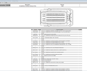
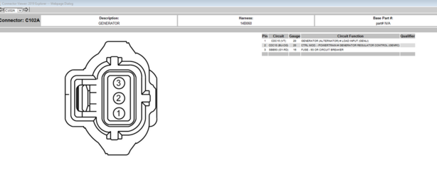
B) does anyone have the connector diagram for the PCM. I have the wiring diagram that shows me the connector numbers, but I don't have the connector diagram that shows me where those numbers are on the connector?

Thanks for your time.


Join the Elite Explorers for $20 each year.
Elite Explorer members see no advertisements, no banner ads, no double underlined links,.
Add an avatar, upload photo attachments, and more!
.


Check out the links on this member's ( J_C) post; ABS issue

Peter


The 2014 documents are too old for a 2019. The general logic of the circuits will be either the same or very similar but most of the specifics of the connectors will be different.

I do have the 2019 documents, I'll see if I can upload them later.

Questions:

1. How did you test the battery and alternator?
2. Have you scanned the PCM for fault codes? If not, you should do so before doing anything else.


Check out the links on this member's ( J_C) post; ABS issue


Peter, appreciate the link. The wiring diagram is very in depth. However the section that is titled "Connector views" which is what I'm looking for, only gives a list of connectors not the actual views.

The attachment is what I'm looking for


Peter


It's a very in depth wiring diagram. Hoowever the section labeled as "connector views"
The 2014 documents are too old for a 2019. The general logic of the circuits will be either the same or very similar but most of the specifics of the connectors will be different.

I do have the 2019 documents, I'll see if I can upload them later.

Questions:

1. How did you test the battery and alternator?
2. Have you scanned the PCM for fault codes? If not, you should do so before doing anything else.
Tested with a multimeter. Yes scanned for codes. Comes up with the generic P0620-00 code. Battery tester tested good, also shows charge system testing good. Battery has 12 volts, after starting goes to around 13.90 then down to 13.20 then back up to 13.55. So to me it is charging, but seems to be intermittent which is common with this open circuit issue between alternator and PCM


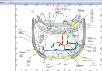
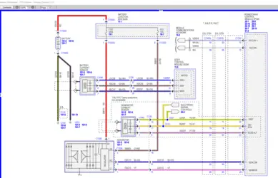
This stuff should get you started.

1) A quick test is to disconnect the 3-wire connector and then run the engine. The internal regulator should self-regulate charging voltage to 13.8 volts. If it doesn't, the regulator is faulty.

2) If you have a scan device that allows you to monitor PCM PIDs, there's another quick test you can make to test the PCM and the GENMON and GENCOM signal lines. On that same 3-wire connector disconnected, jumper the GENMON and GENCOM lines together. Run the engine and monitor those two PIDs. If that portion of the overall circuit is functional, you'll see the two PIDs show the same value that changes up and down in lockstep.

3) Make sure you follow pinpoint F and don't skip testing the battery sense circuit (F93) UNDER LOAD.

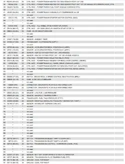
2023-01-10 12_43_07-Service Information - C__TSO_tsocache_OPTIPLEX-5060_8332_SKN~us~en~file=sk...png 2023-01-10 12_41_04-Location Viewer_ 2019 Explorer.png 2023-01-10 12_36_20-Service Information - 2019 Explorer - Charging System (12-1).png2023-01-10 12_39_11-Connector Viewer_ 2019 Explorer --Page 1 of.png 2023-01-10 12_40_06-Connector Viewer_ 2019 Explorer -- 2 of 3.png2023-01-10 12_40_28-Connector Viewer_ 2019 Explorer -- 3 of 3.png


2023-01-10 12_37_03-Connector Viewer_ 2019 Explorer -- Webpage Dialog.png
 

Attachments

  • 2019 Explorer Charging System Pinpoints.pdf
    1.3 MB · Views: 115


This stuff should get you started.

1) A quick test is to disconnect the 3-wire connector and then run the engine. The internal regulator should self-regulate charging voltage to 13.8 volts. If it doesn't, the regulator is faulty.

2) If you have a scan device that allows you to monitor PCM PIDs, there's another quick test you can make to test the PCM and the GENMON and GENCOM signal lines. On that same 3-wire connector disconnected, jumper the GENMON and GENCOM lines together. Run the engine and monitor those two PIDs. If that portion of the overall circuit is functional, you'll see the two PIDs show the same value that changes up and down in lockstep.

3) Make sure you follow pinpoint F and don't skip testing the battery sense circuit (F93) UNDER LOAD.

View attachment 437999 View attachment 438000 View attachment 438005View attachment 438003 View attachment 438002View attachment 438001


View attachment 438004
Thank you so much. Will get to this tonight. Appreciate the help. Figures all this happens 2,000km after warranty is up. Just replaced the MAP sensor last week too


This stuff should get you started.

1) A quick test is to disconnect the 3-wire connector and then run the engine. The internal regulator should self-regulate charging voltage to 13.8 volts. If it doesn't, the regulator is faulty.

2) If you have a scan device that allows you to monitor PCM PIDs, there's another quick test you can make to test the PCM and the GENMON and GENCOM signal lines. On that same 3-wire connector disconnected, jumper the GENMON and GENCOM lines together. Run the engine and monitor those two PIDs. If that portion of the overall circuit is functional, you'll see the two PIDs show the same value that changes up and down in lockstep.

3) Make sure you follow pinpoint F and don't skip testing the battery sense circuit (F93) UNDER LOAD.

View attachment 437999 View attachment 438000 View attachment 438005View attachment 438003 View attachment 438002View attachment 438001


View attachment 438004
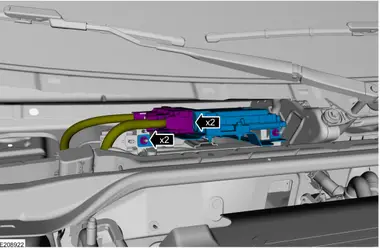
The photos that show the location of the PCM, is this under some sort of cowl or housing? I couldn’t find this when looking there last night


Yes, it is. Instructions attached.
 

Attachments

  • 2019 Explorer Cowl Panel R&I.pdf
    552.7 KB · Views: 85
  • 2019 Explorer Cowl Panel Grille R&I.pdf
    493.7 KB · Views: 107
  • 2019 Explorer Windshield Wiper Pivot Arm R&I.pdf
    834.3 KB · Views: 72


This stuff should get you started.

1) A quick test is to disconnect the 3-wire connector and then run the engine. The internal regulator should self-regulate charging voltage to 13.8 volts. If it doesn't, the regulator is faulty.

2) If you have a scan device that allows you to monitor PCM PIDs, there's another quick test you can make to test the PCM and the GENMON and GENCOM signal lines. On that same 3-wire connector disconnected, jumper the GENMON and GENCOM lines together. Run the engine and monitor those two PIDs. If that portion of the overall circuit is functional, you'll see the two PIDs show the same value that changes up and down in lockstep.

3) Make sure you follow pinpoint F and don't skip testing the battery sense circuit (F93) UNDER LOAD.

View attachment 437999 View attachment 438000 View attachment 438005View attachment 438003 View attachment 438002View attachment 438001


View attachment 438004
So it came down to the blue/orange wire being no good. Continuity test showed the violet was good, b/o had nothing. Clipped in my tone tester from my days of being a phone repair tech. Signal gets lost under the cowl. So there must be a break in there somewhere. Jumped the pcm to the alternator with a different wire. Didn’t have any 20 gauge on hand, now the car won’t start and it tells me blind spot is off and is off, whole bunch of stuff


Blown fuses??


No idea what that means exactly.

My usual course of action is, I f I did something and it causes new problems, undo and get back to where you were before. Best tip I can give you with the sparse information provided.


Back
Top