BrooklynBay's electric scooter project. | Ford Explorer Forums - Serious Explorations

  • Register Today It's free!

BrooklynBay's electric scooter project.

BrooklynBay

Moderator & long time member.
Staff member
Moderator
Elite Explorer
Joined
November 11, 2005
Messages
56,732
Reaction score
1,195
City, State
Brooklyn, NY
Year, Model & Trim Level
88 89 93 95 96 Aerostars
A few weeks ago I was walking around the neighborhood, and found an electric scooter that was in bad condition. It was thrown out because it has a burned out speed controller, rust, was missing batteries, the charger, screws, etc. The cost of one of these scooters is around $80 on sale, and $112 at the regular price so it's not worth investing the same amount of money or possibly more to repair it instead of getting a new one.

I wanted to modify it, and put it to good use getting around the congested neighborhood where it's impossible to find parking. I know that it was originally intended to be a kid's recreation toy but not for long. :D Here's what I plan to do with it:

1. Remove anything that isn't necessary.
2. Add a bench seat, foot controls, and power accessories.
3. Upgrade the electrical system from 24 volts to 36 volts with 2 Ryobi 18 volt battery packs. The original batteries were lead acid according to online information. I have Ryobi 18 volt lithium ion batteries from my tools. Ryobi makes 40 volt batteries but I don't have them or a charger.

So far since I've found it a few weeks ago, I've been gathering information about electric scooters, golf carts, electric bikes, and other types of electric vehicles, and I feel that this project has potential to be a useful means of local transportation.
 

Attachments

  • Razor scooter..jpg
    Razor scooter..jpg
    59.5 KB · Views: 459


Join the Elite Explorers for $20 each year.
Elite Explorer members see no advertisements, no banner ads, no double underlined links,.
Add an avatar, upload photo attachments, and more!
.


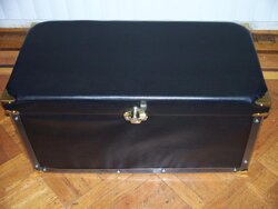
I found a vinyl imitation Ottoman 30" storage box cheap on EBay. The whole thing is very thin, and is designed to fold flat into a box. I had to construct a 3/8" plywood inner box to give it extra strength without adding a lot of extra weight. I didn't install the hinge, lid supports or locks yet.

The interior dimensions are 29" long X 14" wide X 13 1/2" deep (top to bottom measurement). Here are the dimensions of the 3/8" plywood planks:

(2) 28 1/4" long X 13 1/8" deep (sides).
(2) 14" wide X 13 1/8" deep (front & back).
(1) 14" wide X 29" long (bottom).
 

Attachments

  • Ottoman box..jpg
    Ottoman box..jpg
    46.1 KB · Views: 415
  • Ottoman box next to the wood interior..jpg
    Ottoman box next to the wood interior..jpg
    50.4 KB · Views: 424
  • Ottoman box with a wood interior..jpg
    Ottoman box with a wood interior..jpg
    40 KB · Views: 430


Time for another update. 2 locks were installed on both sides of the box, and 2 lid supports were installed inside the box. 2 Ryobi P704 18 volt flashlights came in the mail. They are going to be used as battery sockets. I couldn't find instructions online about removing the front lens to replace the bulb so I'm posting a photo which shows how to pop out the front lens assembly.
 

Attachments

  • The storage box has 2 locks..jpg
    The storage box has 2 locks..jpg
    44.3 KB · Views: 431
  • The storage box with lid supports..jpg
    The storage box with lid supports..jpg
    45.5 KB · Views: 427
  • Ryobi P704 bulb removal..jpg
    Ryobi P704 bulb removal..jpg
    71.6 KB · Views: 447


My local Ace Hardware had 3 different types of brass edge corners. The 1 3/4" brass corners were chosen for the chest since they were the largest size. I was originally going to use metal edging all around but decided to use clear plastic. They had 2 sizes for that so the larger size was chosen.
 

Attachments

  • Side view of the chest with edging..jpg
    Side view of the chest with edging..jpg
    48.8 KB · Views: 410
  • Chest with edging..jpg
    Chest with edging..jpg
    41.4 KB · Views: 431


Watching American ingenuity with interest.


I removed a lot of old stuff from the scooter. The metal cage on the bottom wasn't necessary since there's a large storage area above it, so I cut it off, sanded the frame, and then painted the marks. The trunk was connected to the scooter with screws going into PVC planks. I had to use PVC planks as shims to level the area for the box. I drilled a 1 inch hole, then used a 3/4" PVC bushing on both sides for the wiring from the motor to enter the box. Hot melt glue was used to reinforce the bushings.
 

Attachments

  • Interior view of the box with a bushing..jpg
    Interior view of the box with a bushing..jpg
    51.6 KB · Views: 416
  • Bottom view of the scooter with a bushing..jpg
    Bottom view of the scooter with a bushing..jpg
    31.7 KB · Views: 426


I was thinkin' you'd mount the bench sideways . . . More butt space and you won't have to spread your legs!


The next step was to design a foot base plate for the pedal to sit on. This wasn't an easy task since I had to take numerous measurments, cut, sand, paste, and join parts from 3-1/2" X 3/4" & 5-1/2" X 3/4" PVC planks. Two mending strip plates were used to join 4 pieces together as well. This entire process would have been simplified, stronger, and lighter if I had access to CAD software, and a 3D printer which I don't have either of.
 

Attachments

  • Foot pedal base plate..jpg
    Foot pedal base plate..jpg
    43.9 KB · Views: 432
  • Foot pedal base plate with measurements.jpg
    Foot pedal base plate with measurements.jpg
    77.5 KB · Views: 406


Lowe's has self stick skid guard tread which is made in the USA, and is high quality. Two pieces were used to cover the entire foot base plate. The material feels like course sandpaper with a smooth reflective yellow stripe. I used a sharp utility knife & table top paper cutter to cut everything to size.
 

Attachments

  • Foot pedal base plate with non skid tread..jpg
    Foot pedal base plate with non skid tread..jpg
    91.4 KB · Views: 407
  • Non skid tread..jpg
    Non skid tread..jpg
    118.8 KB · Views: 412


A few of the accessories came in the mail. One of them is a useful item for measuring power usage, Volts, and Amps. It's a 150 Amp power analyzer. The part number is FT08. It doesn't come with any mounting hardware or a way to mount it. I had an extra plastic divider from an organizer toolbox which fits perfectly on the back of it. I used a glue gun to connect it to a handlebar mounted cellphone case.

The wiring will have to be done so wire gauge vs length vs current draw is an important step. I found a good chart online which I'll attach to this post as a PDF.
 

Attachments

  • FT08 power analyzer..jpg
    FT08 power analyzer..jpg
    85.6 KB · Views: 409
  • Cellphone case with power analyzer..jpg
    Cellphone case with power analyzer..jpg
    82.4 KB · Views: 389
  • Wire guage selection chart for 12 Volts DC..JPG
    Wire guage selection chart for 12 Volts DC..JPG
    71.6 KB · Views: 480
  • Wire gauge selection table for 12 Volts DC..pdf
    81.5 KB · Views: 405


I just caught this thread. Very cool project:chug:


Thanks Rick. I did some more work to it but didn't get around to taking pictures. I started to draw schematic diagrams for the wiring today with a program that I downloaded called Circuit Maker student edition. So far I rewired the power analyzer, mounted the cellphone holder, USB socket, cigarette lighter socket, and the foot pedal mounting plate.


I was fortunate enough to find another two more of these scooters this month. One looked like it was left outside most of the time, and had a lot of rust. The other one was rust free. Both of them have a lot of spare parts which were used for this project. I started with a Razor series 41. The second one is a series 41, and the third is a series 44 with some updated parts which fit on mine (with a little work).

I was going to add a diode into the circuit for regenerative braking which is good but only adds a little more voltage into the system while coasting. My next step is to add a spare motor to be used as a generator to add voltage into the system while accelerating as well as coasting.

The chain uses a spring loaded tensioner/idler wheel combination to keep the chain snug. I checked the bolt pattern where the cover, and the tensioner are, and it looks like it matches the motor. The metal frame is in the way, so it needs to be cut.
 

Attachments

  • Generator location..jpg
    Generator location..jpg
    63.8 KB · Views: 383
  • Motor with chain drive..jpg
    Motor with chain drive..jpg
    58.2 KB · Views: 383


That is a handy chart. I just printed it out for reference.


The two extra scooters were put to good use for experimentation, and spare parts. Both of them were combined into a test bed for the generator section. I didn't want to cut the frame of the project scooter so I cut one of the spare parts scooters. I wanted to see if it's possible to connect a motor as a generator. The results were surprising. I connected 3 test batteries (each one was a different voltage) to turn the drive motor on the test bed. The generator will turn at the same speed as the drive motor. The output of the generator matched the voltage of the test battery in each test! Since both motors were the same, it appears that the actual driving voltage will match the output of the generator. I was only testing DC which is lower than AC since the bridge rectifier reduces voltage.
 

Attachments

  • Experimental generator test bed..jpg
    Experimental generator test bed..jpg
    74.2 KB · Views: 378
  • The test bed is next to the scooter..jpg
    The test bed is next to the scooter..jpg
    60.5 KB · Views: 350


The test bed scooter had one screw from the generator connected through the frame. The screw closer to the drive motor was only a pressed fit against the generator to keep it from moving. I had to modify the generator before I transferred it to the main scooter to make it more reliable. I didn't want it to get loose from vibration. I drilled a small hole in the generator, then used a tap to match the thread of the other bolts.

The generator had to be connected with one bolt to mark the location for the new hole with a machine thread. I removed the generator after marking it, carefully drilled a hole, tapped it, then installed the generator with 2 screws, washers, and lock washers. The mounting plate on the generator is aluminum so it was easy to work with. The hole on the iron frame had to be slightly enlarged for the new bolt to go through without resistance. The generator is now preset (no chain adjustment). The automatic chain tensioner was removed, and the generator is in its place.

The shaft on the generator was a little short, so I had to add a washer behind the drive gear to align it with the chain.
 

Attachments

  • Modified generator..jpg
    Modified generator..jpg
    47.4 KB · Views: 365
  • The generator is installed..jpg
    The generator is installed..jpg
    71.1 KB · Views: 370


I hope someone can shoot some video of you riding it :D


Join the Elite Explorers for $20 each year.
Elite Explorer members see no advertisements, no banner ads, no double underlined links,.
Add an avatar, upload photo attachments, and more!
.


I didn't get a chance to work on it in a while so it's time for another update. I made a full wave voltage rectifier module for the generator.
 

Attachments

  • Full wave bridge rectifier module..jpg
    Full wave bridge rectifier module..jpg
    82.6 KB · Views: 345


Back
Top